Smooth Siphon
The problem with the first siphon simulation models was that they simply freely accelerated upwards before being sharply braked when maximum radial velocity was reached, and they then lifted new payloads very sharply off the surface of the Earth one after the other, and cut them free from the top of siphon. The result was a set of very large oscillations travelling up and down the siphon.
The smooth siphon model removes almost all of these radial oscillations. It does this in 3 ways:
- The siphon is not permitted to accelerate freely from a standing start, but is instead constrained to slow linear acceleration. The result of this is that no hard application of brakes happens, and very little oscillation results.
- New payloads aren't pulled up by the rising siphon, but are instead fired up to its radial velocity before hooking onto it. This removes another source of large radial oscillations. Of course, it means that work has to be done to accelerate payloads up to speed - but since the siphon brakes can generate power, a siphon can in principle power the acceleration of payloads upwards, and so no external work may need to be done.
- The radial oscillations that result from releasing payloads from the top of the siphon are far smaller than these first two, but are still significant. One solution is to release payloads little by little, in small masses. This alone suggests that siphons should consist of chains of closely-spaced small masses rather than widely-spaced large masses.
The net result is an almost well-behaved, oscillation-free siphon. But a further change has been necessary. The early siphon models all had fixed-length ties between payloads, and used an arbitrary fixed spring constant to calculate elastic forces. But once the lowest tie began to be paid out slowly, its spring constant changed as the tie lengthened. To calculate this required that ties be given a modulus of elasticity and a cross-sectional area, so that tension forces be correctly calculated:
F = l . A . x / L
where F is tension force (N), l is modulus of elasticity (Pa), A is cross-sectional area, L is free or natural length, and x is extension above free length. The spring constant, k in the equation
F = k . x
is expanded so that k = l . A / L, so that as a tie lengthens, the spring constant k decreases.
Below is the smooth siphon applet. It takes a long time to get running at full speed. To start, move cursor off the applet window. To stop, move cursor over applet window.
|
|
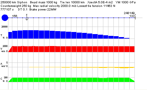
Below is a snapshot of the siphon after it has reached a full speed of 2 km/sec:

|
This simulation model uses only the laws of motion, gravity, and elasticity. To maintain radial motion, calculated payload tangential velocities are discarded, and fixed to r . w.
The simulation shows that the tension distribution in a rising siphon remains much the same as a static tower, with tension maximum at synchronous. And the radial velocities show that, despite only being braked at the base, a fairly constant radial velocity is maintained along the length of the siphon.
Apart from tie tension T, payload radial velocity V, and radial acceleration A, this applet also shows the transverse backward-pushing Coriolis forces exerted along the length of the tower. These forces are not calculated using the formula Fc = 2 . m . w . v, but instead the discarded calculated tangential velocities are recovered and used to calculate tangential acceleration and the tangential Coriolis forces along the length of the siphon. These are, as might be expected, more or less constant along its length. The reason that Coriolis forces fall at the top is because mass is being lost at this point.
One puzzling feature that emerges is that there is a slight decceleration along the length of a rising siphon. No explanation is offered for this. The decceleration appears immediately the simulation starts and remains thereafter, and so would appear to be inherent in the simulation.
The simulation also shows the brake power output, which is given by T . V, where T is the tension in the lowest tie, and V the tie feed rate.
The smooth siphon simulation model is of a rigid radial siphon. Further numerical simulations indicate that if a non-rigid siphon is constrained to very slow acceleration up to full speed, the mass chain will deflect back from radial against the direction of rotation, but will continue to raise masses. However, it appears that the heavier the masses, and the higher the radial speed, the greater the deflection. So such non-rigid siphons appear to have a restricted mass flow.
